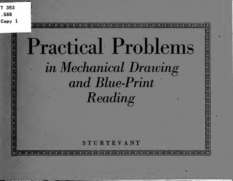
Practical problems in mechanical drawing and blueprint reading by Sturtevant Walter W

Author:Sturtevant, Walter W. [from old catalog]
Language: eng
Format: epub, pdf
Tags: Blueprints, Mechanical drawing
Publisher: Minneapolis, Minn. : Practical problems co.
Published: 1921-03-25T05:00:00+00:00
dimensioned. The extension lines should extend about 3/16 of an inch beyond the arrow heads of the dimension lines.
The dimensions that appear on a drawing should be those' of the object regardless of the scale of the drawing.
Figures should be plain arid not too small. A common mistake of beginners is to confuse minuteness with neatness. Figures should be neat but not smaller than 1/8 of an inch in height.
From 3/16 to 1/8 of an inch ^s good size. Do not use fancy figure's. Plain readable figures that allow of no mistake are best.
Dimensions should be given in the fractions of an inch that are given on the machinists' scale, halves, fourths, eighths, etc., to sixty fourths. Other fractions should be given in decimals as 1.33" or 2.23". In some drafting rooms decimals are used entirely.
It is customary in many drafting rooms to + .003, give a limit of accuracy, as 4. — .0 , meaning that the finished object may exceed 4 inches by not more than 3/1000 of an inch.
4. — .005 means that the object may be 5/1000 smaller, but no larger.
4. + .003 would indicate that the finished piece might be either 3/1000 larger or 3/1000
smaller; but must not exceed that limit.
Fractions should be made with the line between the numerator and the denominator horizontal, not slanting. Thus J, not 1/4. The slant line allows the possibility of a mistake, as in 1 5/16 or 15/16.
Dimensions should, if possible', be kept off of the drawing and placed at the side or between views. A good drawing should stand out clearly and each dimension line placed on it adds to the confusion.
Give the diameters of circles and the' radii of arcs. Diameters should be followed by the abbreviation, Diam., Dia., or D.; radii, by Rad. or R.
Diameters are usually given for circles because a round object is usually turned on the lathe and the workman will measm'e with calipers. If the radius is given on the drawing, he must multiply that by two and might make a mistake.
Holes are drilled with drills marked according to their diamete'rs, as %", 1", etc.
Arcs are laid out with the compasses or dividers and the workman must use the radius.
Never place dimensions on a drawing so that it is necessary for the shop man to make calculations. Do not ask him to add several dimensions in orde'r to get the total. Do not
Download
Practical problems in mechanical drawing and blueprint reading by Sturtevant Walter W.pdf
This site does not store any files on its server. We only index and link to content provided by other sites. Please contact the content providers to delete copyright contents if any and email us, we'll remove relevant links or contents immediately.
Whiskies Galore by Ian Buxton(41741)
Introduction to Aircraft Design (Cambridge Aerospace Series) by John P. Fielding(33032)
Small Unmanned Fixed-wing Aircraft Design by Andrew J. Keane Andras Sobester James P. Scanlan & András Sóbester & James P. Scanlan(32703)
Aircraft Design of WWII: A Sketchbook by Lockheed Aircraft Corporation(32181)
Craft Beer for the Homebrewer by Michael Agnew(18097)
Turbulence by E. J. Noyes(7911)
The Complete Stick Figure Physics Tutorials by Allen Sarah(7281)
The Institute by Stephen King(6883)
Kaplan MCAT General Chemistry Review by Kaplan(6842)
The Thirst by Nesbo Jo(6776)
Bad Blood by John Carreyrou(6502)
Modelling of Convective Heat and Mass Transfer in Rotating Flows by Igor V. Shevchuk(6371)
Learning SQL by Alan Beaulieu(6179)
Weapons of Math Destruction by Cathy O'Neil(6099)
Man-made Catastrophes and Risk Information Concealment by Dmitry Chernov & Didier Sornette(5894)
Permanent Record by Edward Snowden(5701)
Digital Minimalism by Cal Newport;(5603)
Life 3.0: Being Human in the Age of Artificial Intelligence by Tegmark Max(5418)
iGen by Jean M. Twenge(5344)
