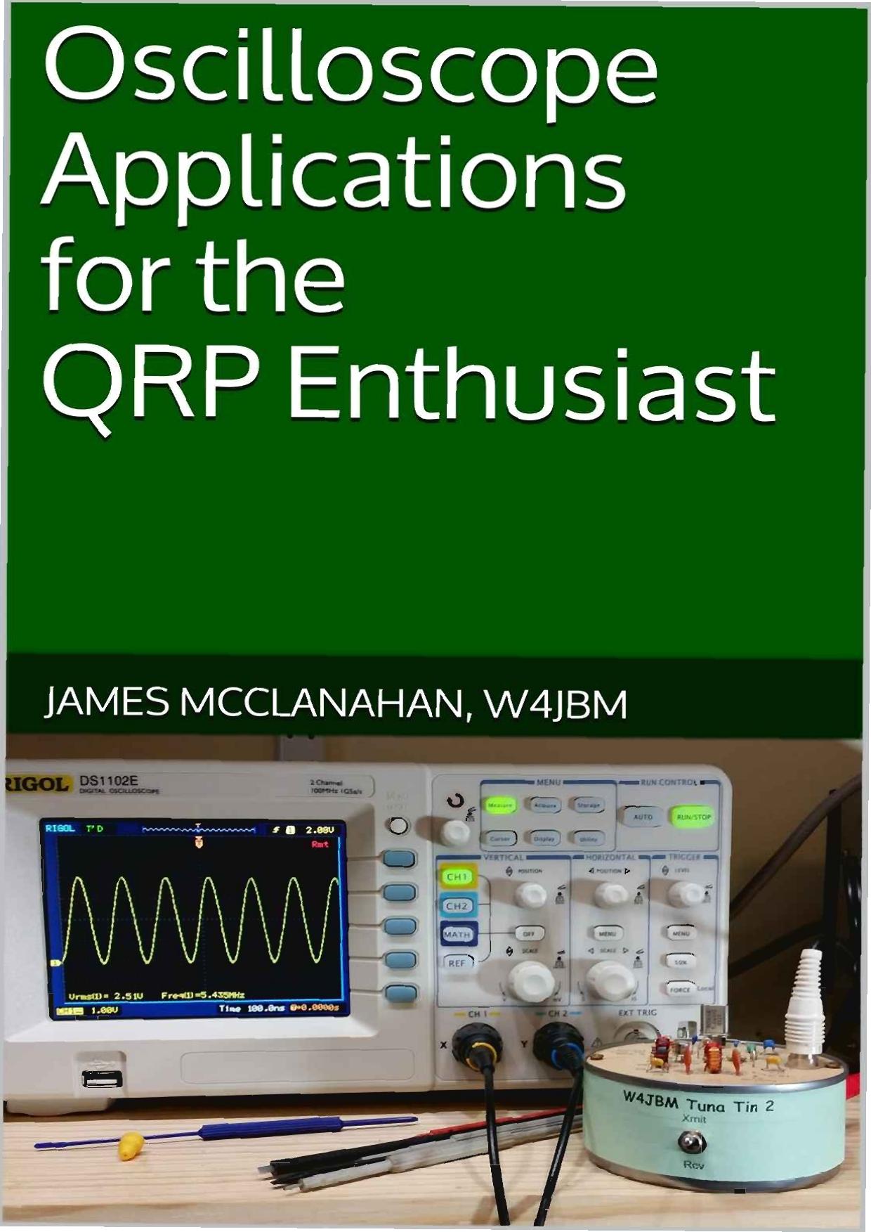
Oscilloscope Applications for the QRP Enthusiast by James McClanahan

Author:James McClanahan [McClanahan, James]
Language: eng
Format: azw3, epub, pdf
Published: 2015-06-04T16:00:00+00:00
You have 12 volts output from the 7812 regulator and that feeds the transmitter. So, if things are working, with Channel 1 connected as shown, you should see 12 volts DC. Make sure Channel 1 coupling is set to DC and that you have the right probe division factor programed in the scope.
Channel 2 is connected so that all of the current flowing "back" into the supply goes through a 1 ohm resistor. With a current of 1 amp, you would see a 1 volt drop. With a current of 0.5 amps, you would see a 0.5 volt drop. The only trick here is that the voltage will be negative with respect to ground. To correct for this, most digital scopes will let you "invert" a channel. So Channel 2 coupling should be set to DC and set to "invert". Also make sure you have the right division factor for the probe programmed in the scope.
If things are right, you should see the voltage on Channel 2 read something under a hundred millivolts when the transmitter is keyed.
For the Tuna Tin 2, I read 69 millivolts on Channel 2 which equates to a current of 69 milliamps.
In our earlier testing we found that the Tuna Tin 2 gave us 603 milliwatts output at 12 volts. Now we can see that at 12 volts we have to "feed" the rig 69 milliamps of current. The input power is the input voltage (12 volts) multiplied by the input current (69 milliamps) which yields 828 milliwatts.
So we put 828 milliwatts of DC power into the Tuna Tin 2 and get 603 milliwatts out. That means we convert the power to RF with an efficiency of about 73% (603 milliwatts divided by 828 milliwatts). Most simple QRP transmitters are going to be in the 60% to 75% efficiency range, so the Tuna Tin 2 is doing fairly well.
When you start measuring input power for transceivers or more advanced rigs, things may not be as straight forward. For example, the FOXX-3 transceiver uses a T/R relay that draws power on transmit. The power consumed by the relay would not normally be considered when calculating transmitter efficiency. Also if there are things like dial lamps or other components drawing current, they would typically not be considered. But, at the same time, they do need to be taken into account when sizing the power supply's current rating or evaluating how the transceiver might drain a battery.
This kind of get at another reason there was a shift from using DC input power to RF output power. When stand-alone transmitters were the norm it was fairly straight forward. But for a more advanced rig you need to design the ability to measure input power to the finals in from the start or it can be difficult to measure.
If you see drastically lower efficiency (less than 50%), take a careful look at the design and the construction of your rig. Something may be amiss. If the input power gets up
Download
Oscilloscope Applications for the QRP Enthusiast by James McClanahan.epub
Oscilloscope Applications for the QRP Enthusiast by James McClanahan.pdf
This site does not store any files on its server. We only index and link to content provided by other sites. Please contact the content providers to delete copyright contents if any and email us, we'll remove relevant links or contents immediately.
| Automotive | Engineering |
| Transportation |
Whiskies Galore by Ian Buxton(40332)
Introduction to Aircraft Design (Cambridge Aerospace Series) by John P. Fielding(32338)
Small Unmanned Fixed-wing Aircraft Design by Andrew J. Keane Andras Sobester James P. Scanlan & András Sóbester & James P. Scanlan(32141)
Craft Beer for the Homebrewer by Michael Agnew(17446)
Turbulence by E. J. Noyes(7039)
The Complete Stick Figure Physics Tutorials by Allen Sarah(6638)
Kaplan MCAT General Chemistry Review by Kaplan(6054)
The Thirst by Nesbo Jo(5785)
Bad Blood by John Carreyrou(5769)
Learning SQL by Alan Beaulieu(5411)
Weapons of Math Destruction by Cathy O'Neil(5036)
Man-made Catastrophes and Risk Information Concealment by Dmitry Chernov & Didier Sornette(4736)
iGen by Jean M. Twenge(4702)
Digital Minimalism by Cal Newport;(4541)
Life 3.0: Being Human in the Age of Artificial Intelligence by Tegmark Max(4507)
Audition by Ryu Murakami(4099)
1,001 ASVAB Practice Questions For Dummies by Powers Rod(4038)
Electronic Devices & Circuits by Jacob Millman & Christos C. Halkias(4027)
Pale Blue Dot by Carl Sagan(4001)
