ti :: TMS9900 :: TMS9918 by Unknown
Author:Unknown
Language: eng
Format: epub
<^
AD2
\_AD1
\zz:
-^—
R5^
CaS
W
Q
D
A0-A6
1^
C7^
W
Q
D
A0-A6
Ca5
W Q D A0-A6
CN
CO
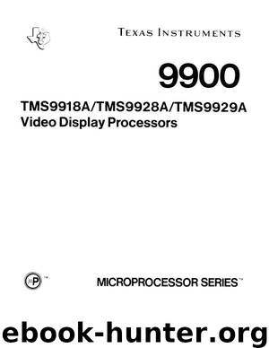
FIGURE 3-1 - VRAM INTERFACE
3.2 VRAM MEMORY ADDRESS DERIVATION
Table 3-2 summarizes the VRAM address derivation for all VDP modes of operation. Section 4 of this manual contains examples of how typical VRAM addresses are computed by the VDP.
TABLE 3-2 ~ PATTERN GRAPHICS ADDRESS LOCATION TABLES GRAPHICS I MODE ADDRESS LOCATION
GRAPHICS II MODE ADDRESS LOCATION
TEXT MODE ADDRESS LOCATION
TABLE 3-2 - PATTERN GRAPHICS ADDRESS LOCATION TABLES (CONTINUED) SPRITE ADDRESS LOCATION
MULTICOLOR ADDRESS LOCATION
The TMS9918A/9928A operates at 262 lines per frame and approximately 60 frames per second in a noninterlaced mode of operation. The TMS9929A operates at 313 lines per frame and approximately 50 frames per second in a noninterlaced mode of operation.
3.3 VRAM ADDRESSING EXAMPLE
A typical application might require up to 256 unique 8x8 patterns with no more than 2 colors per pattern and up to 32 8x8 sprites.
These conditions dictate in which mode the VDP is to be used. The sprite requirement and the 8 x 8 pattern blocks eliminate the text and multicolor modes, respectively. This leaves only the Graphics I and Graphics II modes, and since two colors per block are all that are necessary, Graphics I is employed due to its ease of use.
Figure 3-2 shows a memory map that allows these functions to fit into a 4K memory area.
Register values for Figure 3-2 are as follows:
Register 0 = 00 External VDP disabled, M3 = 0
Register 1 = CO 16K DRAM selected, Blank = 1, Graphics 1 mode selected, SIZE = 0, MAG = 0
Register 2 ^ 01 Name Table Start Address @ >400
Register 3 = 08 Color Table Start Address @ > 0200
Register 4 = 01 Pattern Generator Start Address @ >800
Register 5 = 02 Sprite Attribute Table Start Address > 100
Register 6 = 00 Sprite Pattern Generator Start Address @>0000
Register 7 = XX Determined by user.
If the same application required 16 x 16 bit sprites, then the memory map could be modified as follows:
FIGURE 3-2 - VDP-VRAM MEMORY ALLOCATION
3.4
MONITOR INTERFACES
3.4.1 TMS9918A Monitor Interface
The composite video output signal from the TMS9918A drives a color monitor. This signal incorporates all necessary horizontal and vertical synchronization signals as well as luminance and chrominance information. In monitor applications, the requirements of the monitor should be studied to determine if the VDP can be connected directly to it. The internal output buffer device on the composite video pin is a source-follower MOS transistor that requires an external pull-down resistor to Vgg as shown in Figure 3-3. Typically a 330-ohm resistor is recommended to provide a 1.9-volt synchronization level. The loaa resistor (RL) defines the sharpness of the edges on the video signals. A lower resistor value gives faster fall times and a sharper picture.
In some cases, it may be necessary to provide a simple interface circuit to match the VDP output voltages with the monitor specifications. To drive a standard television that is not outfitted with a composite video input, the signal can be run into the television antenna terminals by using an appropriate RF modulator on the VDP output.
Download
This site does not store any files on its server. We only index and link to content provided by other sites. Please contact the content providers to delete copyright contents if any and email us, we'll remove relevant links or contents immediately.
The Brazilian Economy since the Great Financial Crisis of 20072008 by Philip Arestis Carolina Troncoso Baltar & Daniela Magalhães Prates(362695)
International Integration of the Brazilian Economy by Elias C. Grivoyannis(111602)
The Art of Coaching by Elena Aguilar(53657)
Flexible Working by Dale Gemma;(23362)
How to Stop Living Paycheck to Paycheck by Avery Breyer(19835)
Thinking, Fast and Slow by Kahneman Daniel(12534)
The Acquirer's Multiple: How the Billionaire Contrarians of Deep Value Beat the Market by Tobias Carlisle(12429)
The Radium Girls by Kate Moore(12182)
The Art of Thinking Clearly by Rolf Dobelli(10719)
Hit Refresh by Satya Nadella(9259)
The Compound Effect by Darren Hardy(9153)
Tools of Titans by Timothy Ferriss(8594)
Atomic Habits: Tiny Changes, Remarkable Results by James Clear(8520)
Turbulence by E. J. Noyes(8214)
A Court of Wings and Ruin by Sarah J. Maas(8113)
Change Your Questions, Change Your Life by Marilee Adams(7936)
Nudge - Improving Decisions about Health, Wealth, and Happiness by Thaler Sunstein(7854)
How to Be a Bawse: A Guide to Conquering Life by Lilly Singh(7614)
Win Bigly by Scott Adams(7347)
