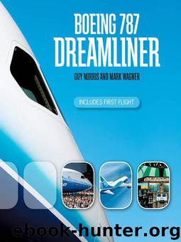
Boeing 787 Dreamliner by Mark Wagner; Guy Norris

Author:Mark Wagner; Guy Norris
Language: eng
Format: mobi
Tags: Transportation, Nonfiction
ISBN: 9781616732271
Publisher: MBI
Published: 2009-11-15T10:00:00+00:00
Here is a view through the Rockwell Collins HGS head-up display looking south along a simulated runway 13 Right at Boeing Field. Altitude is indicated down the right side, and air speed on the left. The notched line top center is the aircraft reference symbol, or boresight, and represents the projected centerline of the 787. Mark Wagner
The inner landing gear cylinders were to be made in Bidos, France, while in Gloucester, United Kingdom, the truck beam or bogie would came together; and in Montreal, Canada, the outer cylinder of the main gear fitting took place. Titanium brake rods for the main landing gear were built at Messier-Dowty’s Suzhou site in China. First metal for the inner cylinders was cut in France in November 2005, and machining of the first truck beams took place through 2006 in Gloucester, and of the main fitting in Montreal. Initial shipsets were assembled in Gloucester, but eventually transitioned to a final integration facility by the Everett site, where all the actuators, wheels, brakes, and other parts would be added before it was “rolled” as a complete subassembly to the production line.
Japanese manufacturer Bridgestone was picked to supply nose and main landing gear radial tires incorporating a new belt structure with “a high-elasticity, high-strength cord that is weight-efficient and wear-resistant,” said Boeing. A second tire supplier also was expected to be certified.
While much of the advanced technology focus was on the electrical systems, significant improvements also were made in more traditional areas, such as hydraulics and fuel. The Parker-developed 787 hydraulics operated at a high pressure of 5,000 psi, compared to the 3,000 psi of most previous systems.
It was made up of three independent systems—left, center, and right, with the center powered by a pair of large electrically driven hydraulic pumps in place of the usual air turbines. The pumps on the center system had capacity for 30 gallons per minute at 5,000 psi and were designed to split duties, with one running constantly and the other kicking in just for peak demands, such as landing-gear or high-lift-system actuation.
Among them the three systems collectively powered the primary flight control actuators, as well as landing gear actuation, nose gear steering, thrust reversers, and the leading and trailing edge flaps. Power for the left and right systems was mostly provided by engine-driven pumps mounted on the engine gearbox, backed up by an electric-motor-driven hydraulic pump for peak demands and for ground operations. As with the A380, A350XWB, and Concorde, the higher-pressure system saved both space and weight on the 787, as it allowed the use of smaller hydraulic components.
In early 2006 Parker ran the first production configuration hydraulic pump at its design ratings of 5,000 psi with zero load, and 4,750 psi at full flow, marking a crucial step toward full-up testing and production go-ahead. Parker supplied the entire hydraulic subsystem through its Kalamazoo, Michigan–based Hydraulic Systems Division. The company’s Nichols Airborne Division supplied liquid-cooling pumps and reservoirs for Hamilton Sundstrand’s primary electronics cooling air management system and “smart pumps” for the Hamilton Sundstrand APU.
Download
This site does not store any files on its server. We only index and link to content provided by other sites. Please contact the content providers to delete copyright contents if any and email us, we'll remove relevant links or contents immediately.
| Airport | Commercial |
| Helicopters | History |
| Pictorial | Piloting & Flight Instruction |
| Repair & Maintenance |
Small Unmanned Fixed-wing Aircraft Design by Andrew J. Keane Andras Sobester James P. Scanlan & András Sóbester & James P. Scanlan(32137)
Navigation and Map Reading by K Andrew(4550)
Endurance: Shackleton's Incredible Voyage by Alfred Lansing(3834)
Wild Ride by Adam Lashinsky(1655)
And the Band Played On by Randy Shilts(1612)
The Box by Marc Levinson(1591)
Top 10 Prague (EYEWITNESS TOP 10 TRAVEL GUIDES) by DK(1563)
The Race for Hitler's X-Planes: Britain's 1945 Mission to Capture Secret Luftwaffe Technology by John Christopher(1523)
The One Percenter Encyclopedia by Bill Hayes(1461)
Girls Auto Clinic Glove Box Guide by Patrice Banks(1357)
Trans-Siberian Railway by Lonely Planet(1337)
Looking for a Ship by John McPhee(1316)
Fighting Hitler's Jets: The Extraordinary Story of the American Airmen Who Beat the Luftwaffe and Defeated Nazi Germany by Robert F. Dorr(1299)
Batavia's Graveyard by Mike Dash(1298)
Troubleshooting and Repair of Diesel Engines by Paul Dempsey(1280)
Bligh by Rob Mundle(1269)
TWA 800 by Jack Cashill(1249)
The Great Halifax Explosion by John U. Bacon(1227)
Ticket to Ride by Tom Chesshyre(1224)
