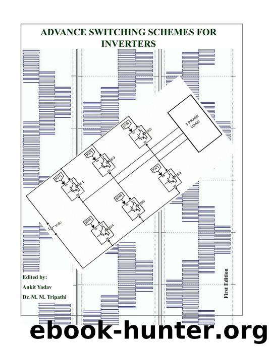
Advance Switching Schemes for Inverters by Yadav Ankit & Tripathi Madan Mohan

Author:Yadav, Ankit & Tripathi, Madan Mohan
Language: eng
Format: epub
Published: 2015-06-19T04:00:00+00:00
Figure 3.7 Single-phase H-bridge VS DC–AC inverter test result (load voltage and load current waveform) for R-L load using PWM switching scheme. Similar to case of load current, harmonics content in load voltage is lesser in results obtained from modified scheme than the results obtained from PWM scheme. The analysis of outcome of both schemes signifies that the modified switching scheme gives better result than the PWM scheme in terms of RMS, peak as well as THD value of voltage and current for given load and operating condition. The observation of RMS and peak values of current, voltage, values of THDs and their waveforms suggest that the modified scheme is better than the PWM scheme under given operating conditions.
3.4.2 Dynamic load (Motor load) The simulation has been performed for motor load also under the previously defined loading conditions. The operating condition and other parameters have been kept identical for both schemes under simulation. The motor used as load is a main and auxiliary winding type motor which specification is described above. This motor has been operated with constant torque of unity during simulation. Voltage and current waveforms obtained by applying PWM scheme is shown in figure 3.11 and waveform obtained using modified switching scheme are shown in figure 3.12. THD graphs from both schemed are presented in 3.13 and 3.14 respectively for voltage and current. The comparative results of simulation of both schemes are in table 3.2.
Download
This site does not store any files on its server. We only index and link to content provided by other sites. Please contact the content providers to delete copyright contents if any and email us, we'll remove relevant links or contents immediately.
| Automotive | Engineering |
| Transportation |
Whiskies Galore by Ian Buxton(41986)
Introduction to Aircraft Design (Cambridge Aerospace Series) by John P. Fielding(33115)
Small Unmanned Fixed-wing Aircraft Design by Andrew J. Keane Andras Sobester James P. Scanlan & András Sóbester & James P. Scanlan(32788)
Craft Beer for the Homebrewer by Michael Agnew(18234)
Turbulence by E. J. Noyes(8040)
The Complete Stick Figure Physics Tutorials by Allen Sarah(7362)
The Thirst by Nesbo Jo(6928)
Kaplan MCAT General Chemistry Review by Kaplan(6926)
Bad Blood by John Carreyrou(6610)
Modelling of Convective Heat and Mass Transfer in Rotating Flows by Igor V. Shevchuk(6431)
Learning SQL by Alan Beaulieu(6277)
Weapons of Math Destruction by Cathy O'Neil(6263)
Man-made Catastrophes and Risk Information Concealment by Dmitry Chernov & Didier Sornette(6002)
Digital Minimalism by Cal Newport;(5747)
Life 3.0: Being Human in the Age of Artificial Intelligence by Tegmark Max(5544)
iGen by Jean M. Twenge(5408)
Secrets of Antigravity Propulsion: Tesla, UFOs, and Classified Aerospace Technology by Ph.D. Paul A. Laviolette(5364)
Design of Trajectory Optimization Approach for Space Maneuver Vehicle Skip Entry Problems by Runqi Chai & Al Savvaris & Antonios Tsourdos & Senchun Chai(5062)
Pale Blue Dot by Carl Sagan(4996)
