0521416043 by Unknown
Author:Unknown
Language: eng
Format: epub
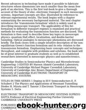
4.1 Origin of 'zero' resistance 183 Fig. 4.1.3. Hall bridge at high magnetic fields showing two edge states at each edge. only if (p—q) is equal to A-6), B-1), C—2), D-3), E-4) or F—5). All other transmission coefficients are zero. Neglecting any backscattering we can write down the conductance matrix (which is pro- proportional to the transmission function) by inspection: Gm: q=l q = 2 q=3 q=A q=5 q=6 0 Gc 0 0 0 0 0 0 Gc 0 0 0 n 0 0 0 Gc 0 0 2e 0 0 0 0 Gc 0 2M 0 0 0 0 0 Gc Gc 0 0 0 0 0 where We can solve for the terminal currents and voltages starting from Eq.B.5.8), which yields a system of six equations. As explained earlier (see discussion preceding Eq.B.4.6)) these equations are not independent and we can choose the voltage at one of the terminals to be zero and omit the row and column corresponding to that terminal. Setting V4 = 0, h h h h h .= Gc -Gc 0 0 0 0 Gc -Gc 0 0 0 0 Gc 0 0 0 0 0 Gc -Gc -Gc 0 0 0 Gc Vi v2 v3 v5 v6
184 Quantum Hall effect We could invert this matrix as we have done in the past, but it is un- unnecessary. We can easily write down the solution to the above set of equations noting that the currents at the voltage terminals are all zero (/2 = /3=/s=/6 = 0): V2-V3-Vu V5=V6=0 This is of course precisely what we had assumed, namely, that any volt- voltage probe on one side floats to a potential equal to the right contact while any probe on the other side floats to a potential equal to the left contact. Also the current is given by /i = GcVi so that the longitudinal resistance RL measured between probes 2 and 3 or between 5 and 6 is zero Л while the Hall resistance Rh measured between probes 2 and 6 or between 3 and 5 has the quantized value stated earlier (see Eq.D.1.5)). _ Vi-Ve Уз-Vs n Rh Gc h h Does the current flow only at the edges? We stated above that if Ц\ > цг (as shown in Fig. 4.1.1) then the states below цг are all filled and do not carry any net current. Any net current can be calculated from the filled states on the left between ц\ and цг- However, this does not mean that current flows only near the edge having the potential цх. There are currents everywhere in the sample. We could choose to do our bookkeeping in a different way so that the net current appears at a different spatial location. We have identified all the states below fi2 (note that ц\ > цг) as our Fermi sea which does not carry any net current. Consequently the net current is carried by electrons in the edge states on one side of the sample with
Download
This site does not store any files on its server. We only index and link to content provided by other sites. Please contact the content providers to delete copyright contents if any and email us, we'll remove relevant links or contents immediately.
Becoming Supernatural by Dr. Joe Dispenza(8277)
Crystal Healing for Women by Mariah K. Lyons(7965)
The Witchcraft of Salem Village by Shirley Jackson(7337)
The Four Agreements by Don Miguel Ruiz(6835)
Inner Engineering: A Yogi's Guide to Joy by Sadhguru(6835)
The Power of Now: A Guide to Spiritual Enlightenment by Eckhart Tolle(5854)
Secrets of Antigravity Propulsion: Tesla, UFOs, and Classified Aerospace Technology by Ph.D. Paul A. Laviolette(5412)
The Wisdom of Sundays by Oprah Winfrey(5206)
Room 212 by Kate Stewart(5183)
Pale Blue Dot by Carl Sagan(5080)
Fear by Osho(4781)
The David Icke Guide to the Global Conspiracy (and how to end it) by David Icke(4771)
Rising Strong by Brene Brown(4512)
Animal Frequency by Melissa Alvarez(4510)
How to Change Your Mind by Michael Pollan(4401)
Sigil Witchery by Laura Tempest Zakroff(4295)
Man and His Symbols by Carl Gustav Jung(4194)
The Art of Happiness by The Dalai Lama(4167)
Real Magic by Dean Radin PhD(4166)
