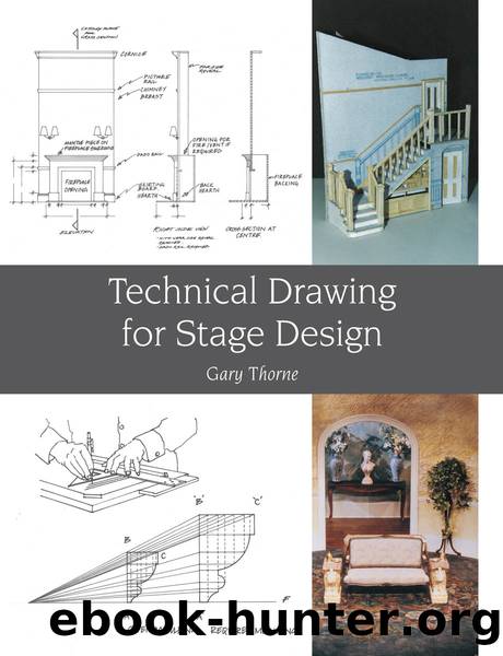
Technical Drawing for Stage Design by Gary Thorne

Author:Gary Thorne
Language: eng
Format: epub
ISBN: 9781785000669
Publisher: The Crowood Press
2.
Print the number between the lines, with the line interrupted by a space.
With the second method, the line actually continues, yet is faintly drawn for the locating of centre of numbers as a guideline. Above and below the centre line will be guidelines set 5mm apart in parallel.
Notes about dimensions
Always draw guidelines for numerical dimensioning.
Where there is a long dimension line, it may be necessary to allow space between the parallel lines of a dimension line and object profile, for inclusion of intermediate dimensions.
When dimensions are layered in a parallel manner, with some set beyond the others, avoid alignment of the numerical dimensions; instead, numerical dimensions should be staggered slightly.
Place a dimension alongside the view which best explains its true characteristic. Look for the most obvious place to plot relevant height, width or depth measurements.
With views being placed alongside one another, a dimension may relate to both views, therefore include it only once between those two views.
All dimensions need including which facilitate the viewer comprehending the object. The viewer should not need to calculate dimensions. Avoid duplicating a dimension.
Expressing numerals in dimensions
All dimensions should consistently be in millimetres (1m is printed as 1000, 10cm is printed as 100, 2cm is printed as 20, 1.5cm is printed as 15). It is not necessary to put âmmâ after a dimension. Do not mix centimetres into the drawing. For measurements larger than 1000mm, print in the same millimetre format (100cm is printed as 1000, 200cm is printed as 2000, 1000cm is printed as 10000). Measurements less than 10mm may have the millimetres included: 9mm, 8mm through to 1mm.
Draughting for theatre construction calls for precision, yet it is not so common to find complex refined dimensions in a drawing (such as 1751mm, 153mm, 27mm) unless a material is of a specific thickness or size known to the draughtsman. However, bench drawings or construction drawings â those prepared by Head of Construction or an engineer â show fine-tuned millimetre dimensioning, appropriate to the materials being used in construction. The designer tends to be mainly concerned with key proportional measurements.
Generally print numerical measurements at 5mm height wherever possible. If they are below 3mm they will be difficult to read. The more effort one has to make to read dimensions, the more likely there will be miscalculations.
Where a dimension is printed alongside a drawing that is not at scale, there should be written alongside the drawing, âNOT TO SCALEâ.
Dimensions of curved shapes
Circle
Depict a circle centre with a cross (a vertical and horizontal line intersecting), using a set-square and the horizontal of the T-square. To add in radii:
1.
Draw an inclined straight line as a âpointer lineâ from outside the circumference to beyond, and where the pointer touches the circumference draw an arrow. At the other end of the pointer line print the letter âDâ and add in the diameter measurement.
Download
This site does not store any files on its server. We only index and link to content provided by other sites. Please contact the content providers to delete copyright contents if any and email us, we'll remove relevant links or contents immediately.
Eats, Shoots & Leaves by Lynne Truss(1325)
Nickel and Dimed by Barbara Ehrenreich(1126)
Midnight's children by Salman Rushdie(1007)
The Imaginary Invalid by Molière(995)
Bring Up the Bodies by Hilary Mantel(869)
Black Coffee (Poirot) by Agatha Christie(835)
The 500 by Matthew Quirk(801)
The Seagull by Anton Chekhov(800)
The Lovely Bones by Sebold Alice(796)
Buried Child by Sam Shepard(752)
Steven Berkoff by Steven Berkoff(730)
An Ideal Husband by Oscar Wilde(721)
The Bourgeois Gentleman (World Classics) by Molière(719)
The Comedy Bible by Judy Carter(661)
Profiles by Tynan Kenneth; Tynan Kathleen;(658)
Finding Roger by Rick Elice(651)
Tobacco Road by Erskine Caldwell(635)
The Guys by Anne Nelson(598)
Mrs. Warren's Profession by George Bernard Shaw(589)
