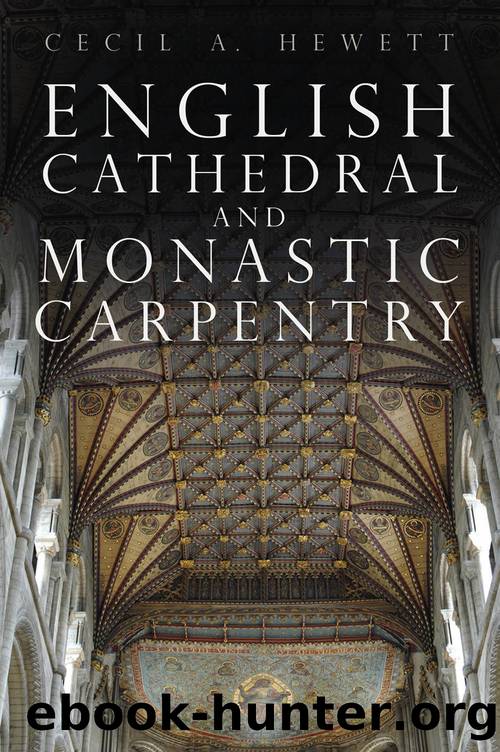
English Cathedral & Monastic Carpentry by Cecil A. Hewett

Author:Cecil A. Hewett
Language: eng
Format: epub
Publisher: The History Press
109. Ely Cathedral, the angle post of the lantern.
The method used for construction can be deduced from the fabric, the masonry shell providing certain evidence for the former quantities of heavy timbers that are now absent. As shown in the following series of diagrams, there was no baffling sequence of assembly, such as it is tempting to envisage. The full-height grooves built into the internal angles of the stone shell were fitted with eight great posts, probably measuring 9 ins. by 11 ins., and 48 ft. in length (Fig. 109). These were retained, apparently, by the timber tie-backs which were let into the stone hooks at either side of each channel, and thereafter the side-timbers framing the octagon-plan were inserted between the posts, rendering them immovable. This cannot be proved owing to the ravages of decay, boring insects and restorers, but it is highly probable. Timber imposts for the springing of the numerous vault-ribs were fitted to these posts, and rested, of course, on the upper stone surface of the piers. These remain in situ, but have been carved away on their interior surfaces to eradicate beetle, and no longer form a sound standing for the ribs â some having buckled sideways, causing an angularity in the originally straight lines of the âvaultâ. The side arches were no problem and were probably fitted without delay, these having a lodging on a projecting stone course throughout their arcature. The bracket-like assemblies illustrated must have been fitted thereafter; the inherited great scaffold (with additions) must have supported these, which examination of their crossing-joints proves to have been placed in two sets of four â perhaps almost simultaneously. The plan, Fig. 110, illustrates the fact that the four sills marked A, C, E and G were placed first, and the other four let into them. This process is further shown in Fig. 111, showing the placing of the second set of four sills in position. This done, the joists steadying the projecting ends of the sills could be fitted, when a perilous degree of stability would have been achieved. The letters used to identify the timbers cut to fit into each of the eight sectors are illustrated in the form of the originals, perhaps cut by Master Hurley. I am indebted to Dr. O. Rackham for the information that all were cut with two scribes, one for straight cuts and the other for inch and a quarter circles â hence the curious forms of the letters (personal communication, 1979). Fig. 112 shows the structure when the first 24 ribs were fitted, and some stability achieved, whereafter the many tierceron-ribs would have followed, each being fitted simultaneously with the joist supporting it. The distribution of the joists in each sector is shown in Fig. 113, from which it must be noted that every joist had a lap-dovetailed outer end-joint, to resist withdrawal after the weight of its rib had been suspended from its inner end â against the octagonal inner sill. The âvaultâ and the integral floor to the 70 ft.
Download
This site does not store any files on its server. We only index and link to content provided by other sites. Please contact the content providers to delete copyright contents if any and email us, we'll remove relevant links or contents immediately.
The Second Coming of Saturn: The Great Conjunction, Americaâs Temple, and the Return of the Watchers by Derek P. Gilbert(121)
The origins of violence by John Docker(117)
Llewellyn's 2024 Sabbats Almanac by Llewellyn Publishing(85)
English Cathedral & Monastic Carpentry by Cecil A. Hewett(85)
668113337 by Unknown(75)
The Healing Power of Kindness âVolume 1: Releasing Judgment by Kenneth Wapnick(72)
The Church of the Covenant 1637-1651 by Walter Makey(69)
Being, While Knowing That You Are Not: Surrendering to the sadness and madness of life (Reality Explained Trilogy Book 2) by Marc Leavitt(69)
THE ORIGIN OF ALL RELIGIOUS WORSHIP by DUPUIS(68)
Tao of Wing Chun Do by (Volume 2 Chi Sao)(67)
Pain Is Inevitable, Misery Is Optional by Hyrum W. Smith & Gerreld L. Pulsipher(65)
642916429 by Unknown(65)
Lillian Too's Irresistible Feng Shui Magic by Lillian Too(63)
The Knights Templar and their myth by Peter Partner Murdered magicians(63)
The Lesser Key of Solomon by Samuel Liddell MacGregor Mathers(62)
Pseudepigrapha of the Old Testament as Part of Christian Literature: The Case of the Testaments of the Twelve Patriarchs and the Greek Life of Adam and Eve by Marinus de Jonge(61)
978-3-031-46661-8 by Unknown(60)
Code of Canons of Oriental Churches by The Catholic Church(59)
Llewellyn's 2023 Sabbats Almanac by Elizabeth Barrette(58)
