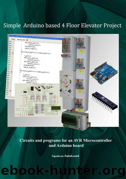
Simple Arduino based 4 Floor Elevator project by Seyedreza Fattahzadeh
Author:Seyedreza Fattahzadeh [Fattahzadeh, Seyedreza]
Language: eng
Format: epub
Published: 2015-04-03T22:00:00+00:00
Figure 1-4
Functional explanation of part # 6: hoist and car door fixture
In Figure 1-2 the piece of fixture that is designated as # 6, is the mechanism designed to simulate Elevator’s hoist (at the top) and car door motors. To view this project in action, you may click on the following link:
http://youtu.be/UQbGcntcVP4
Simulating the host lift and car door motors
The disk on the top of the fixture (see Figure 1-5) simulates the up or down car movement of the elevator easily. There is a cabin of lift which will be moved up or down across different floors, with the help of a small DC motor which its shaft mounted to the center of a disk. In this project of lift, a single motor is used which will turn the disk clock or anticlockwise. When the disk is turning clockwise, it is simulating downward car movement. On the contrary, when it is being turned anticlockwise, it is simulating upward car movement.
This project is simulating operation of a lift with four stops. For floor detection and to generate an arrival signal of the car to any selected stop, four slotted optocouplers are used (4 pieces shown in blue color). For this project, I needed four photo interrupters- each is a small device that shines a light from one side to the other, where there is a detector.
The idea is that if anything breaks the light beam, you take note of it, and use the information (signal) as you wish. In my case, I am using a disk which has a small rectangular area cut off from it, thus the beam will be broken except for that one 'spot'. I have installed four optocouplers around the disk corresponding to four floors. Thus, when the cut in section creates an interrupt at any related optocoupler, Microprocessor deletes the stop number and performs appropriate action accordingly. I used a total of six slotted optocouplers in this lift implementing project, one sensor for each stop and two more to detect if the car door is open or closed.
The half disk located at the bottom of the piece # 6 is related to opening and closing mechanism of the car door. Notice again that I have used two more optocouplers to detect if the door is open or closed. When sensor # 5 is interrupted (= 0) but sensor # 6 is uninterrupted (= 1), the status of the door is 'open'. To close the door, controller has to activate the door motor in anticlockwise (in the direction shown with the blue arrow) to cause Sensor # 5 = 1and Sensor # 6 = 0.
Download
This site does not store any files on its server. We only index and link to content provided by other sites. Please contact the content providers to delete copyright contents if any and email us, we'll remove relevant links or contents immediately.
| AI & Machine Learning | Bioinformatics |
| Computer Simulation | Cybernetics |
| Human-Computer Interaction | Information Theory |
| Robotics | Systems Analysis & Design |
Algorithms of the Intelligent Web by Haralambos Marmanis;Dmitry Babenko(20886)
Jquery UI in Action : Master the concepts Of Jquery UI: A Step By Step Approach by ANMOL GOYAL(11883)
Test-Driven Development with Java by Alan Mellor(7863)
Data Augmentation with Python by Duc Haba(7719)
Principles of Data Fabric by Sonia Mezzetta(7496)
Learn Blender Simulations the Right Way by Stephen Pearson(7422)
Microservices with Spring Boot 3 and Spring Cloud by Magnus Larsson(7232)
Hadoop in Practice by Alex Holmes(7066)
RPA Solution Architect's Handbook by Sachin Sahgal(6632)
The Infinite Retina by Robert Scoble Irena Cronin(6345)
Big Data Analysis with Python by Ivan Marin(6050)
Life 3.0: Being Human in the Age of Artificial Intelligence by Tegmark Max(5697)
Pretrain Vision and Large Language Models in Python by Emily Webber(5029)
Functional Programming in JavaScript by Mantyla Dan(4777)
Infrastructure as Code for Beginners by Russ McKendrick(4771)
WordPress Plugin Development Cookbook by Yannick Lefebvre(4538)
The Age of Surveillance Capitalism by Shoshana Zuboff(4439)
Embracing Microservices Design by Ovais Mehboob Ahmed Khan Nabil Siddiqui and Timothy Oleson(4250)
Applied Machine Learning for Healthcare and Life Sciences Using AWS by Ujjwal Ratan(4230)
