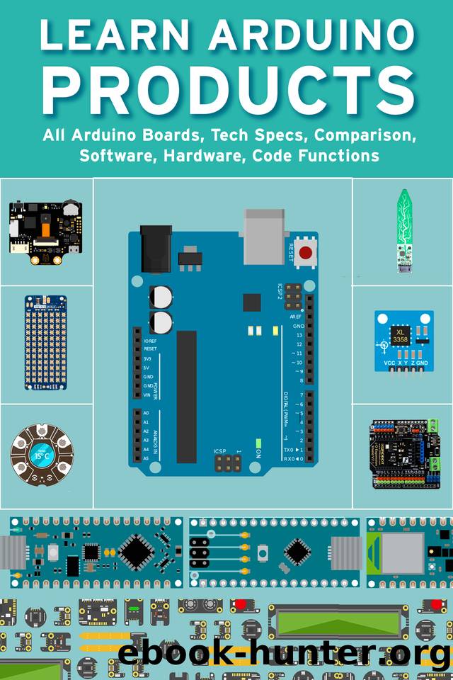
LEARN ARDUINO PRODUCTS: All Arduino Boards, Tech Specs, Comparison, Software, Hardware, Code Functions by Janani Sathish

Author:Janani Sathish [Sathish, Janani]
Language: eng
Format: azw3, epub
Published: 2021-05-07T00:00:00+00:00
RELATED BOARDS
If you still decide about the right wireless protocol for your solution, the Arduino MKR family has several alternatives to offer:
⢠MKR FOX 1200: For your EU solution in SigFox infrastructure. Visit the product page here.
⢠MKR WAN 1310: If you want to experiment with Lora® or Lorawan â¢. Read more here. We also have a Lora® gateway if you bring up your own infrastructure.
⢠MKR NB 1500: If your solution is designed around IoM Narrowband. Read more about it here.
START
The starting section contains all the information you need to configure your board, use Arduino software (IDE), and start playing with coding and electronics. If you want to know more about Arduino's Mkrgsm API, check this reference page.
ANTENNA
When purchased at Arduino Store, MKR GSM 1400 bundled with an antenna that can be attached to the board using the existing Micro UFL connector. It is possible to use other antennas using the appropriate pigtails.
When buying an antenna that is different from the provided (or when creating it yourself), please check whether it is set for the frequency band used in the GSM / 3G range. Also avoid placing your antenna in parallel with ground planes such as large metal surfaces.
BATTERIES, PINS, AND BOARD BOARDS
⢠Battery capacity: Li-ion refill, or Li-Po. Make sure the battery connector is in accordance with your battery.
⢠Battery connector: The connector is the type of JST S2B-PH-SM4-TB (LF) (SN). The wedding connector is the JST PHR-2.
⢠VIN: This pin can be used to raise the board with setting 5V resources. If the power is fed through this PIN, USB resources are disconnected. This is the only way you can provide 5V (5V range to a maximum of 6V) to the blackboard does not use USB. This pin is input.
⢠5V: This pin produces 5V from the board when supported from the USB connector or from the PIN VIN board. Not set and voltage taken directly from the input.
⢠VCC: This pin produces 3.3V through the on-board voltage regulator. This voltage is 3.3V if USB or VIN is used.
⢠LED on: This LED is connected to 5V input from USB or VIN.
⢠Onboard LED: On the GSM 1400 LED onboard MKR connected to D6.
TECH SPECS
Microcontroller
SAMD21 Cortex®-M0+ 32bit low power ARM MCU (datasheet)
Download
LEARN ARDUINO PRODUCTS: All Arduino Boards, Tech Specs, Comparison, Software, Hardware, Code Functions by Janani Sathish.epub
This site does not store any files on its server. We only index and link to content provided by other sites. Please contact the content providers to delete copyright contents if any and email us, we'll remove relevant links or contents immediately.
The Mikado Method by Ola Ellnestam Daniel Brolund(22431)
Hello! Python by Anthony Briggs(21622)
Secrets of the JavaScript Ninja by John Resig Bear Bibeault(20183)
The Well-Grounded Java Developer by Benjamin J. Evans Martijn Verburg(19309)
Kotlin in Action by Dmitry Jemerov(19233)
OCA Java SE 8 Programmer I Certification Guide by Mala Gupta(18772)
Algorithms of the Intelligent Web by Haralambos Marmanis;Dmitry Babenko(17575)
Grails in Action by Glen Smith Peter Ledbrook(16726)
Sass and Compass in Action by Wynn Netherland Nathan Weizenbaum Chris Eppstein Brandon Mathis(14219)
Test-Driven iOS Development with Swift 4 by Dominik Hauser(10923)
Windows APT Warfare by Sheng-Hao Ma(7848)
Layered Design for Ruby on Rails Applications by Vladimir Dementyev(7561)
Blueprints Visual Scripting for Unreal Engine 5 - Third Edition by Marcos Romero & Brenden Sewell(7464)
Solidity Programming Essentials by Ritesh Modi(4582)
Functional Programming in JavaScript by Mantyla Dan(4508)
Hands-On Full-Stack Web Development with GraphQL and React by Sebastian Grebe(4445)
WordPress Plugin Development Cookbook by Yannick Lefebvre(4404)
Unity 3D Game Development by Anthony Davis & Travis Baptiste & Russell Craig & Ryan Stunkel(4272)
The Ultimate iOS Interview Playbook by Avi Tsadok(4265)
